How to Choose a Horizontal Tensile Testing Machine
Choosing a horizontal tensile testing machine starts with the specimen, not the catalogue. A wide geotextile roll, a webbing strap, and a narrow film strip each demand different grips, travel, and force capacity. Get those details wrong, and a sophisticated load cell will not rescue the test.
ASTM E4 and ISO 7500-1 offer recognized guidance for force verification and machine calibration. They help buyers assess measurement reliability, but they do not determine which frame suits a particular production line. Check the expected peak load, test speed, crosshead travel, specimen width, and grip design. Also ask how the machine handles long samples and whether operators can mount them without twisting. Small alignment errors matter. So does the space around the frame.
Lord Kelvin, the physicist known for his work on measurement, wrote, “When you can measure what you are speaking about, and express it in numbers, you know something about it.” That principle fits tensile testing well. A clear force-displacement curve is useful only when the setup and calibration support it. It is easy to overlook. In practice, buyers should compare repeatability, software, safety features, service access, and data export alongside headline capacity. Some requirements remain uncertain until real samples are tested; that uncertainty deserves a trial run, not a confident guess. This guide explains how to weigh those factors and choose a horizontal tensile testing machine that fits the material, workflow, and evidence your team needs.
Identify the Materials, Loads, and Test Standards
Choosing a horizontal tensile testing machine starts with the specimen, not the frame.
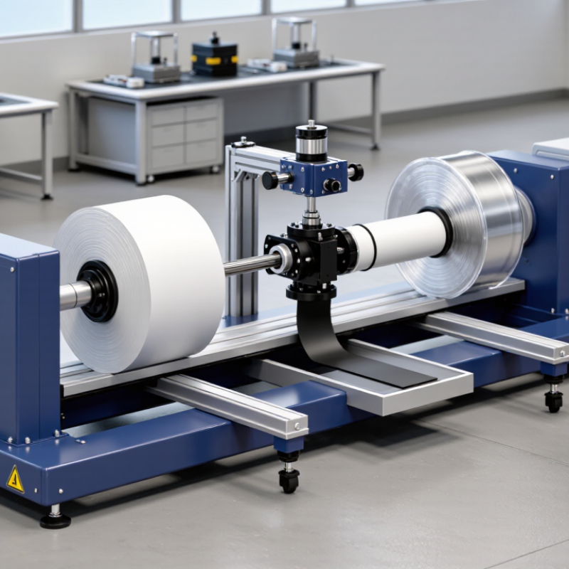
List the materials you will test, such as woven webbing, wire, polymer film, or long metal sections. Note specimen length, width, thickness, and how it may stretch or slip. A strap that creeps in the grips needs a different setup from a rigid bar. Small details matter.
Estimate the maximum force before comparing machine capacities.
Include the load expected at failure, but avoid choosing a capacity so large that ordinary tests use only a tiny portion of the measurement range. Check the load cell, grip opening, crosshead travel, and available space for long samples. Ask how the machine handles alignment; a slight angle can distort results. It happens more easily than expected.
Then identify the exact test standard and edition required by your application.
Confirm specimen preparation, conditioning, pulling speed, gripping method, and reporting rules against the method itself. Standards can differ even when they test similar materials. Make sure the machine’s controls and accessories can reproduce those requirements, and keep calibration records. One assumption is worth questioning: a familiar setup is not automatically a compliant one.
Compare Horizontal Frame Capacity and Specimen Dimensions
Choose the frame around the specimen and the force it must carry, not the headline capacity alone. ASTM E8/E8M specifies a common round tensile specimen with a 12.5 mm diameter and 50 mm gauge length. ISO 6892-1 gives proportional specimens a gauge length of 5.65 times the square root of cross-sectional area. These dimensions affect grip choice, fixture clearance, and extensometer placement. Check the full specimen length, including shoulders and tabs, against the machine’s usable span.
Then estimate peak force: tensile stress multiplied by specimen area. A 12.5 mm round bar has about 122.7 mm² of area; at an assumed 400 MPa strength, its peak load is roughly 49 kN. That is a calculation, not a material guarantee. A 100 kN frame may suit this example, but the load cell’s useful range, grip rating, and required safety margin still matter. Small details count.
For long cable, webbing, or component tests, verify grip opening, crosshead travel, and alignment under load. A frame can have ample force capacity yet be too short for the specimen and fixtures. Ask for a dimensioned drawing and confirm the complete setup before ordering. I would recheck the actual specimen batch too: nominal dimensions can hide variation that changes the required load.
How to Choose a Horizontal Tensile Testing Machine - Compare Horizontal Frame Capacity and Specimen Dimensions
| Selection profile |
Typical force-capacity range |
Suggested clear test length |
Approximate overall frame length |
Common specimen examples |
Key selection checks |
| Compact |
Up to about 50 kN |
0.5–1.5 m |
About 2–3 m |
Short wire, cord, small cable, and narrow strip specimens |
Check grip compatibility, alignment, and whether the working stroke allows for grip movement and specimen extension. |
| General-purpose |
About 50–250 kN |
1.5–4 m |
About 3–6 m |
Rope, strand, reinforcing elements, and medium-length cable samples |
Confirm maximum force at the required test speed, usable crosshead travel, and the working envelope for grips and fixtures. |
| Long-specimen |
About 100–500 kN |
4–10 m |
About 6–12 m |
Long wire rope, cable, chain, and structural tie specimens |
Allow space for specimen extension, grip length, loading hardware, safe access, and any required guarding. |
| Heavy-duty / extended frame |
About 250–1,000 kN or more |
8–20 m or more |
About 12–25 m or more |
Large-diameter wire rope, heavy chain, and long structural components |
Check foundation and floor loading, frame stiffness, calibration range, safety enclosure, and installation clearances. |
|
Planning note: The capacities and dimensions above are indicative selection ranges, not standardized machine ratings. “Clear test length” means the usable distance between the specimen gripping points; overall frame length is greater because of the load frame, actuators, and end fixtures. Confirm the required force, specimen length and extension, grip arrangement, test speed, and site clearances with the equipment supplier before specifying a machine.
|
Evaluate Grips, Fixtures, and Measurement Systems
For a horizontal tensile testing machine, choose grips that match the specimen’s shape, material, and expected load. Flat jaws may suit sheet samples, while wedge or wrap grips can help hold round or flexible materials. The specimen should stay centered as the load increases, without slipping or being crushed at the jaws. Small details matter. Check jaw width, surface texture, and opening range against the samples you actually test, not just a catalog diagram. A fixture that works for one thickness may distort a thinner specimen.
Fixtures also control alignment and support. Long or flexible samples can sag before testing, so suitable supports may help keep them straight without adding unwanted restraint. A perfect alignment on paper can still hide a slight twist in the specimen. It is worth checking the setup with a representative sample and looking for uneven marks or bending near the grips.
Measurement systems need equal care. Confirm that the load cell covers the expected force range, and select an extensometer or displacement sensor suited to the required strain accuracy. Crosshead travel alone may include machine and grip movement, so it may not represent specimen extension precisely. Not always. Review calibration records, sensor resolution, and how data are captured. Small setup differences can shift results, and that is easy to overlook when a test appears to run smoothly.
Assess Installation, Calibration, and Long-Term Support
A horizontal tensile testing machine needs more than a clear space on the workshop floor. Check the foundation, access route, and room for the full crosshead travel before delivery. Long specimens may extend well beyond the frame. Measure the largest test setup, not just the machine footprint. Confirm that the floor can support the equipment and that power connections match the site requirements. Keep enough clearance to load samples safely and reach emergency controls. A small alignment error can affect results.
Ask how calibration is performed across the load range you actually use. A certificate covering only one point may not reflect routine testing. Check whether the process includes the load cell, extensometer, and relevant fixtures, and whether calibration is traceable to recognized standards. Calibration intervals should reflect usage, risk, and the manufacturer’s guidance. It matters. Long-term support deserves the same scrutiny: confirm technician availability, spare-part lead times, software updates, and operator training. Request written response times. A machine can be accurate on installation day, yet difficult to maintain years later. That detail is easy to overlook. Ask who will help diagnose a drifting reading, and what records they expect you to keep.